
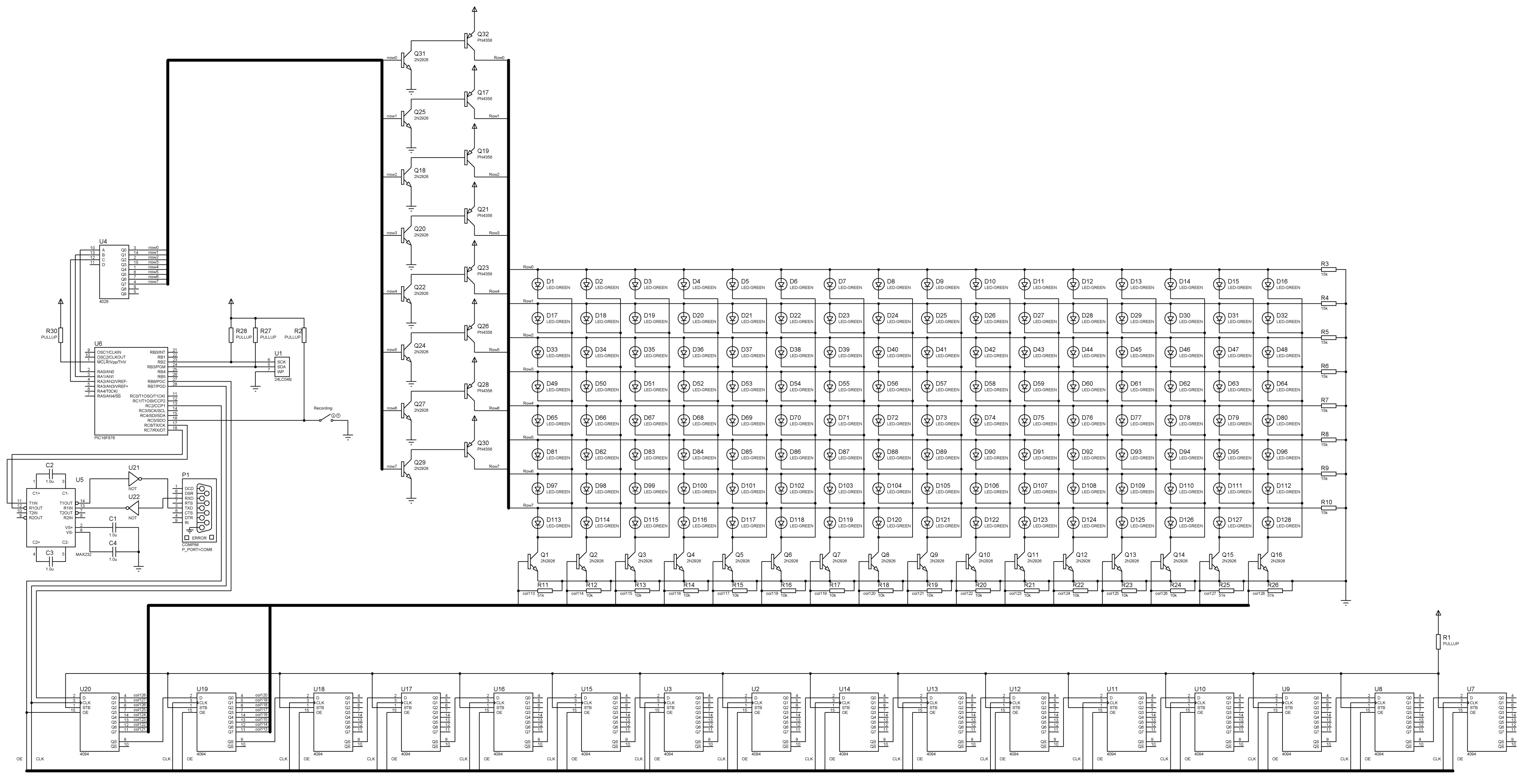
Here is the schematic of 8×128 LED message board and its simulation project for Proteus.
Previous parts of this saga can be viewed here, here, here and here.
A few notes about schematic and simulation:
- For complete simulation you need some additional software in order to communicate with simulation via RS-232.
If you don’t need a full emulation of communication (text upload) process – you can delete MAX232 chip, COMPIM port and connect Proteus Terminal Emulator directly to Tx and Rx pins of the MCU.
I personally used com0com to create virtual connected com ports and Realterm to send hex data into the project. - Inverters U21 and U22 are not needed in a real scheme, but anyway, keep in mind that MAX232 inverts polarity of signals and in some cases they may not be restored on the other side, so you may need inverters or change Rx/Tx polarity programmatically.
- I placed all shift registers on a scheme, but actually only two are used, because I am unable to use large LED matrix in Proteus. I’ve done this to put into perspective the whole idea of the scheme and the order of connections. The LED matrix represents the rightmost part of the message board, assuming the message is moving from right to left.
-
There might be problems with load capacity of the PIC’s pins that are used for clock and OutputEnable controls of shift registers, but I have never encountered them myself.
If you face these problems you may try to connect a few PIC’s pins together and use them as one. For instance, you can join together portc 0,1,2 pins, connect them to OE signal bus and use commands like1 2
movlw b'00000111' movwf portcto control OE.
- There is a controversial question what to do with STR bus for shift registers. I simply put it on the Vcc, but you can connect it to OE or even drive this line by PIC programmatically.
- Firmware for this project is compatible only to 24c04 EEPROM memory, but this restriction is only applied for recording. You can alter “recording” function to fit other types of EEPROM
- There is a switch “Recording” which changes the mode of the system. When switch is closed the PIC is only waiting for data from USART and is transferring it to the EEPROM. The state of the switch is checked at the beginning of each rendering cycle. You can realize that the PIC has noticed closed switch when emulation speed becomes realtime. Emulation speed is very fast in the “Recording” mode.
- In reality this firmware used at 24MHz, so USART timings were set for 24MHz clock speed.
- As in the previous schemes, resistors R3-R10 is a demand of Proteus and I had never used them in the real life.
- Resistors R11-R26 have also never been used in real life but might improve switching characteristics.
- The simulation is slow, very slow, so I reduced the number of frames between column shifts to 4.
This scheme doesn’t differ much from previous schemes.
There are two main distinctions:
- The new microcontroller, which has larger SRAM and Program memory. It leads to increasing complexity of the code because additional memory space is divided into few banks.
- Ability to write data into EEPROM through PIC using RS-232.
The first question is well described in comments inside ASM file, if you are interested.
Regarding the ability of flashing data into EEPROM:
1) There needs to be a custom flash tool with a nice intereface which will convert ascii string from the end user into a byte sequence and send it to a com-port. I had one but now it is outdated so I will only show a proof-of-concept.
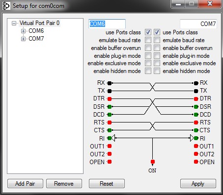
2) To create an emulation as close to reality as possible you need to install com0com. It will create two connected together virtual com ports (let it be COM6 and COM7)
3) You need a convenient terminal emulator, which is capable to send series of hex numbers. I used Realterm.
4) Realterm and COMPIM should be set up for 9600 baud rate, 8 data bit, one stop bit, no parity control, no flow control.
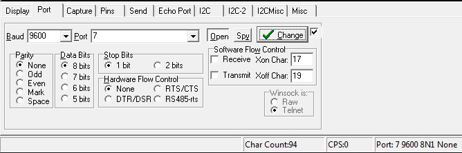
Realterm settings
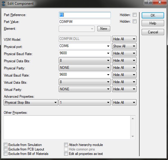
Proteus COMPIM settings
5) COMPIM should be connected to COM6 and Realterm should be connected to COM7 (or vice versa).
6) Once more – inverters U21 and U22 is not needed in real life. As I understand, MAX232 preforms signal inversion and each com port does the same. So, if you attach MAX232 to the PC com port – everything will work fine, but in simulation it seems that COMPIM does not understand inverted signal.
The firmware of the project in “Recording” mode waits for three bytes which then will be transferred to EEPROM.
The first byte is a control byte which always begins with “1010” and always ends with “0” (write operation). Remaining 3 bits are: 2 bits of the device address (I hope you grounded address pins of EEPROM and so, these bits should be “0”) and one bit of the memory address, because 24c04 has 512 bytes of memory and it needs 9 bits to address it.
Please check the datasheet for more information.
The second byte is an address within 256-byte page.
The third byte is a data byte.
So, for example, if you are writing only into first 256 bytes of memory from the beginning, the Control byte is remaining the same – 0xA0, address byte is incrementing from zero, and data codes are equal to ascii codes if you are using the same character generator. For the message “hello world!” we will have sequence:
1 2 3 4 5 6 7 8 9 10 11 12 13 | 0xA0 0x00 0x68 ; h 0xA0 0x01 0x65 ; e 0xA0 0x02 0x6C ; l 0xA0 0x03 0x6C ; l 0xA0 0x04 0x6F ; o 0xA0 0x05 0x20 ; 0xA0 0x06 0x77 ; w 0xA0 0x07 0x6F ; o 0xA0 0x08 0x72 ; r 0xA0 0x09 0x6C ; l 0xA0 0x0a 0x64 ; d 0xA0 0x0b 0x21 ; ! 0xA0 0x0c 0xCC ; start over |
0xCC is a command for message board to start over.
To program this phrase into the EEPROM you have to close “Recording” switch, wait for the PIC to become ready and then send space-separated hex digits to com-port as one line. That’s it.
0xA0 0x00 0x68 0xA0 0x01 0x65 0xA0 0x02 0x6C 0xA0 0x03 0x6C 0xA0 0x04 0x6F 0xA0 0x05 0x20 0xA0 0x06 0x77 0xA0 0x07 0x6F 0xA0 0x08 0x72 0xA0 0x09 0x6C 0xA0 0x0a 0x64 0xA0 0x0b 0x21 0xA0 0x0c 0xCC |
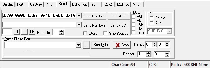
sending process in Realterm
There is no any check of data integrity or EEPROM operation status (ready or busy because of writing), but I have never encountered any errors, furthermore, I haven’t used any delays in clock subroutines, which are, nevertheless, present in the current firmware…
All notes about character generator and symbol codes from the previous project are valid, but now we have more space for symbol images and we place them into a separate bank ( after org 0x800 directive).
Now, the part of character generator, which reads codes from EEPROM, can recognize a special symbol 0xCC which means that the whole process should be started over (string runs from the beginning).
It is useful, when you have a string much smaller than EEPROM size.
Downloads:
ASM file.
HEX file for flashing PIC.
EEPROM initial ‘binary’ file for EEPROM.
CHARGEN character generator written on Perl.
Project file for Proteus 8.4