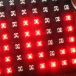
As I mentioned earlier, PIC16F84 does not allow to create a good 8×64 message board because of its RAM amount.
So my next approach was simply to replace PIC16F84 on PIC16F876 and use its larger RAM.
The real 8×64 board worked using PIC16F876 chip.
Its firmware almost the same as in the previous article, but it uses more RAM.
The fact that RAM in PIC16F876 is splitted into four banks shouldn’t be important because the first bank of the RAM contains 96 GPRs which should be enough for a 8×64 matrix.
The next stage (after the first, the second and moving to 16-876 chip) was 8×128 LED message board.
It was made by using the same technique as all previous test boards.
The screen was made from an oblong list of plastic.
The front side of this screen was painted in black color.
There were 1024 holes about 4.5-5 mm each that were drilled equidistantly in that plastic. Their diameter allowed them to hold tightly a typical cheap 5mm LED.
At the back of she screen all connections between LEDs were made by their soldered pins (legs).
There were no resistors – only direct row and column connections which eventually lead to 8 row and 128 column pins.
Controller consisted of two development boards.
One of them for ICs and the other for transistors.
I have no images of this message board or its screen in assembled, working state, but I have a few images of the controller boards 🙂
This message board contains:
PIC16F876 in DIP28 case,
128 + 8 transistors similar to 2N4123,
8 power transistors similar to BD140 for row switching,
16 shift registers similar to 4094
one decimal decoder,
one EEPROM memory up to 8KB,
one IC similar to MAX232
In this version the procedure of EEPROM programming was changed.
In the previous versions EEPROM had to be programmed by an external flasher, which needed to understand I2C protocol and specific commands for EEPROM.
In the current version all programming is done via PIC.
You send data to PIC via RS232 interface and then PIC sends them to EEPROM.
To be continued…