
This is the next improvement, part three, to the simple LED message board.
Here you can see the first and the second parts.
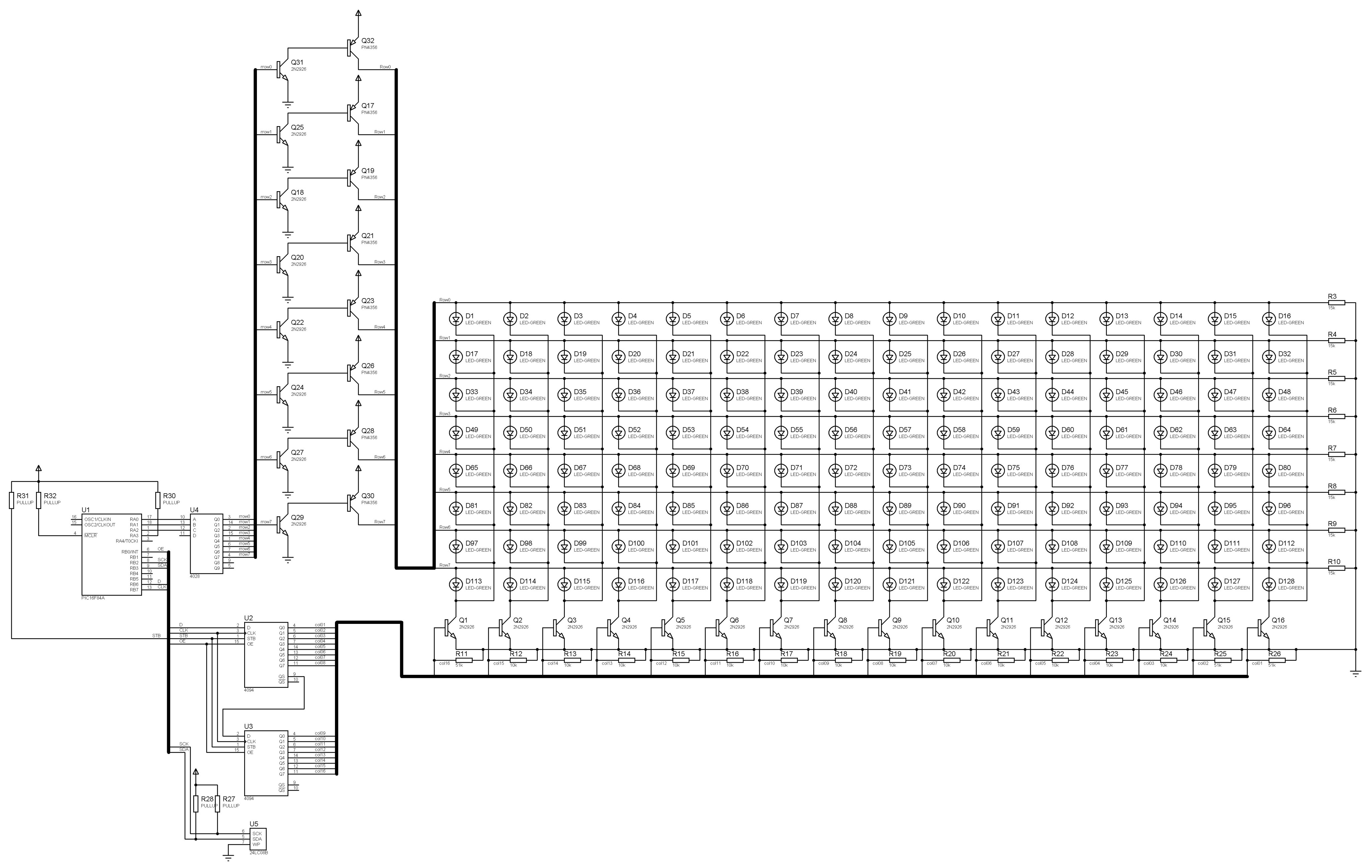
The new schematic diagram has a few changes:
Now it seems to me that the code of this project looks like a palisade 🙂
There is a huge number of repeating identical structures.
They makes me nervous, I can’t look at them and want to roll them up into cycle, but I won’t 🙂
As I remember I tried to do some compactification of code but didn’t succeed.
For now I have no hardware device and am compelled to rely on a slow (very slow) Proteus simulation.
So I can’t really debug any significant code changes and therefore I left it intact as much as I can.
Due to changes in connections I had to reverse and invert all bytes that represent LEDs and also I had to change an alphabet (code page) because originally it was russian.
I’ve checked a few frames so basically it does work.
This version of message board has some improvements.
1) It has attached EEPROM chip, so we have a large additional memory storage. I think any I2C EEPROM can be connected. I personally used 8K 24LC08.
2) I have hopped over the stage where I used EEPROM which contained the image of the string, i.e. 5-8 bytes for a one character. In the current version EEPROM contains only the codes of symbols, whereas the images of the symbols are located in PIC’s program memory as a slightly ugly subroutines. An 8-bit encoding (some kind of ASCII) is used to store a data on EEPROM.
Notes about charset:
– Despite the fact, that I call this board “8×16”, actually 5×7 font is used, so upper row is unclaimed.
– Current system allows you to put into EEPROM a bare text in any ASCII-type encoding. You literally can take Windows notepad, write there “hello world”, save this file in ANSI encoding and then flash it into the real EEPROM or load it into the Proteus EEPROM simulation. Actually, in the EEPROM you will find ASCII codes of your letters.
-To see your string on the LED matrix you need to create a character generator, which will translate EERPOM’s ASCII codes to the letter images.
Character generator itself is situated in the PIC, but its code is large and has to be generated automatically.
I’ve written a sample of this “generator of generator” which has only lowcase ASCII latin letters. It can be extended but not too far, because only about 100 words left free in the program memory. There needs to be some optimization, I think 🙂
Here you can see the reduced version (the full version you can find in the attachment at the bottom of this page):
Perl script
1 2 3 4 5 6 7 8 9 10 11 12 13 14 15 16 17 18 19 20 21 22 23 24 25 26 27 28 29 30 31 32 33 34 35 36 37 38 39 40 41 42 43 44 45 46 47 48 49 50 51 52 53 54 55 56 57 58 59 60 61 62 63 64 65 66 67 68 69 70 71 72 73 74 75 76 77 78 79 80 81 82 83 84 85 86 87 88 89 90 91 92 93 94 95 96 97 98 99 100 101 102 103 104 105 106 107 108 109 110 111 112 113 114 115 116 117 118 119 120 121 122 123 124 125 126 127 128 129 130 131 132 133 134 135 136 137 138 139 140 141 142 143 144 145 146 147 148 149 150 151 152 153 154 155 156 157 158 | #! /usr/bin/perl use strict; use utf8; my $LETTER_WIDTH = 5; my $font = { 0x00 => [ # zero (spase) [0,0,0,0,0], [0,0,0,0,0], [0,0,0,0,0], [0,0,0,0,0], [0,0,0,0,0], [0,0,0,0,0], [0,0,0,0,0], [0,0,0,0,0], ], 0x20 => [ # space [0,0,0,0,0], [0,0,0,0,0], [0,0,0,0,0], [0,0,0,0,0], [0,0,0,0,0], [0,0,0,0,0], [0,0,0,0,0], [0,0,0,0,0], ], 0x61 => [ # a [0,0,0,0,0], [0,0,0,0,0], [0,0,0,0,0], [0,1,1,1,0], [0,0,0,0,1], [0,1,1,1,1], [1,0,0,0,1], [0,1,1,1,1], ], 0x62 => [ # b [0,0,0,0,0], [1,0,0,0,0], [1,0,0,0,0], [1,0,0,0,0], [1,1,1,1,0], [1,0,0,0,1], [1,0,0,0,1], [1,1,1,1,0], ], 0x63 => [ # c [0,0,0,0,0], [0,0,0,0,0], [0,0,0,0,0], [0,1,1,1,1], [1,0,0,0,0], [1,0,0,0,0], [1,0,0,0,0], [0,1,1,1,1], ], 0x64 => [ # d [0,0,0,0,0], [0,0,0,0,1], [0,0,0,0,1], [0,0,0,0,1], [0,1,1,1,1], [1,0,0,0,1], [1,0,0,0,1], [0,1,1,1,1], ], 0x65 => [ # e [0,0,0,0,0], [0,0,0,0,0], [0,0,0,0,0], [0,1,1,1,0], [1,0,0,0,1], [1,1,1,1,1], [1,0,0,0,0], [0,1,1,1,1], ], 0x66 => [ # f [0,0,0,0,0], [0,0,0,1,0], [0,0,1,0,1], [0,0,1,0,0], [0,1,1,1,0], [0,0,1,0,0], [0,0,1,0,0], [0,0,1,0,0], ], # ---------- CUT HERE ------------- 0x7a => [ # z [0,0,0,0,0], [0,0,0,0,0], [0,0,0,0,0], [1,1,1,1,1], [0,0,0,1,0], [0,0,1,0,0], [0,1,0,0,0], [1,1,1,1,1], ], 0xff => [ # unknown char [0,0,0,0,0], [0,1,1,1,0], [1,0,0,0,1], [0,0,0,0,1], [0,0,0,1,0], [0,0,1,0,0], [0,0,0,0,0], [0,0,1,0,0], ], }; open( my $fh, '>', './chargen.asm') or die "unable to open output file! $! \n"; print $fh ";************** CHARACTER GENERATOR\n"; print $fh "getletter\n"; # label print $fh "\tcall getadd\n";# reading letter's code from EEPROM foreach my $chr (sort{$a <=> $b}keys %$font){ my $hex_chr = sprintf("%x",$chr); print $fh "\tmovlw\t0x$hex_chr\n"; print $fh "\txorwf\tscratch,0\n"; print $fh "\tbtfsc\tstatus,z\n"; print $fh "\tgoto\tltr_0x$hex_chr\n\n"; } print $fh "\tgoto\tltr_0xff\n\n"; # letter not recognized - draw empty space print $fh ";************** LETTER IMAGES\n"; foreach my $chr (sort{$a <=> $b}keys %$font){ my $hex_chr = sprintf("%x",$chr); print $fh "ltr_0x$hex_chr\n"; foreach my $col (1..$LETTER_WIDTH){ my @tmp = (); foreach my $row ( reverse @{$$font{$chr}} ){ push @tmp, $$row[$col-1]; } print $fh "\tmovlw\tb'" . join('', @tmp) . "'\n"; print $fh "\tmovwf\tbuff_$col\n" } print $fh "\tgoto\tbuff\n\n"; } |
So, If you want to change or to extend a font, that used in the message board, you need:
1) Change and use Perl character generator script. Place there the new letter matrices, run script and obtain an ASM code fragment for the new code page.
2) Insert generated fragment into the PIC’s firmware source. If you use wider letters – you will also need to change some constants.
Some external tool is needed to program the EEPROM. As I remember I used my own software, written in Delphi for Windows 98, that wrote data into the EEPROM using direct access to the LPT port 🙂
The LPT was connected directly to the EEPROM pins.
Therefore, current asm program contains subroutine “recording” which checks a certain bit in PORTA, that should be set to 0 if external device is trying to write data to the EEPROM.
This approach is unacceptable nowadays, but you can use any flasher (PonyProg for example) and write any ANSI text files into the EEPROM directly.
Proteus doesn’t like this scheme very much. I’ve had strange problems with EEPROM, which sent only 0xFF in response to sequential reads.
I’d changed frequency of PIC from 10MHz to 1MHz and EEPROM started to work properly. After that I raised frequency back to 10MHZ and EEPROM still works.
What was that?
Back in the days, in the real hardware, each my EEPROM worked well on the firmware identical to this project, although subroutines that deals with EEPROM is homemade and have no any delays or timing adjustments. These subroutines without changes worked on PIC16F628@24MHz.
As I remember, I have never encountered any I2C bus errors on the real hardware.
Downloads:
ASM file.
HEX file for flashing PIC.
EEPROM ‘binary’ file for EEPROM.
CHARGEN character generator on Perl.
Project file for Proteus 8.4
I think this firmware can be improved in two ways.
1) You can use computed jump to the list of RETLW instructions.
It will reduce the amount of instruction words needed for letter images.
But as I understand, this microcontroller can perform computed jumps only in the range of 255 bytes.
So, we have to divide our symbol table into the blocks of 32 characters each and then we can perform a
computed jump within this block.
It might reduce the amount of code needed to load character to videoram.
But anyway, one letter consists at least of 5 program words (if I didn’t miss some trick that allows to use program memory for data storage),
and ASCII has about 200 characters. It means that all program memory (1000 words) is needed to store letter images. There is no space for other code no matter how clever and tricky you are 🙂
2) Character images can be stored on the external EEPROM in a specific range of addresses. It would be like a two partitions of EEPROM, the one with alphabet images and the other with a string content or you can connect two different EEPROMs.
This approach requires 16-bit calculations to pick letter image but has no limitations to alphabet itself.
I did not implement these improvements myself.
So, what about expansion to 8×64 matrix size?
It seems that I did something like that.
I didn’t tested THIS code in Proteus, and it won’t work directly, but you can change the project from the current page to this 8×64 code.
The key is to use only 4 GPRs for your own purposes and left the rest 64 for videoram.
It means that there will be no place for hidden videobuffer from which a new letter is shifted on the screen so,
you should store on the EEPROM the image of the string (I think that what I did) and shift the string to videobuffer from the EEPROM column my column.
Or maybe you’ll find a better way 😉