
This is a second post about pieces of hardware for “internet vending machine”. The first post, which describes the whole idea, a presence detector and an audio amplifier is here.
Interceptor is a device that is connected between PC and a keyboard for keyboard data filtering. Device is also capable to receive some data from external sensors and transmit it to PC via serial interface but its main task, which consumes the most of the resources, is keyboard data filtering.
Certain mode of filtering is set from a PC via serial port. There is also default mode which is activated if mode haven’t been configured by PC.
Device is powered from PS/2 port and consumes less than 100mA including keyboard.
Conventions that will be used in the text below:
Host – PS/2 keyboard controller that is situated in a PC
Interceptor – device that is described here.
Interceptor is a multi-functional device that is aimed to control hardware and software of a PC.
Interceptor has 4 connectors:
PS/2 for a keyboard,
PS/2 for a Host,
DB9F/USB for connection to PC serial port
and connector for parallel connection to PC’s reset button.
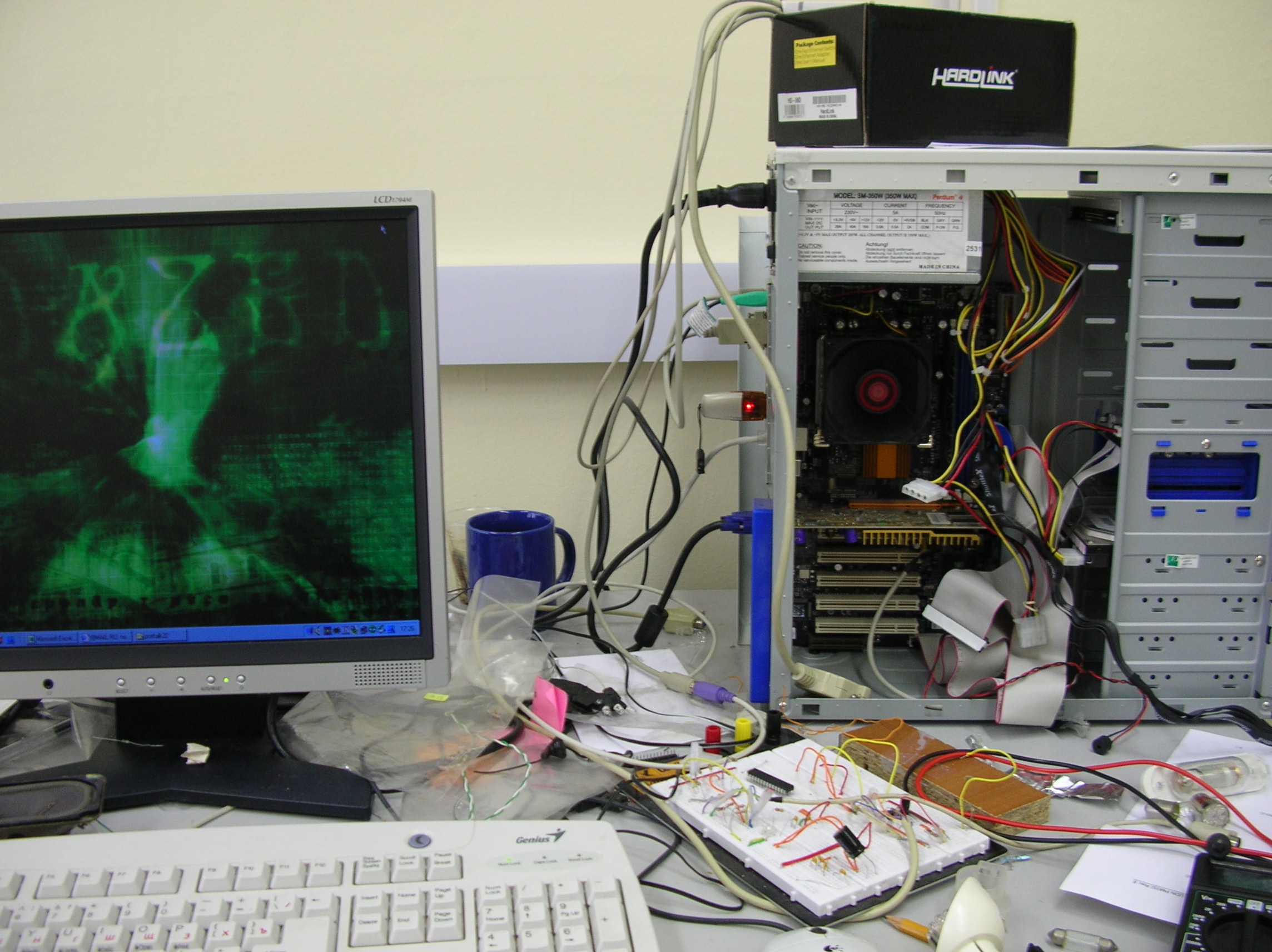
This is the only picture of the device I have. It is in the box from Hardlink switch 🙂
In the latest versions there were also mini-jack connectors for:
– AD22100ST thermal sensor
– LCD power control module
– push button to detect case opening
The main task of this device is to block input from the keyboard during reboot, during the PC hanging and also in some other situations which are determined by the PC software.
With respect to keyboard, the interceptor can be in two modes:
1) commands from Host can be transmitted to keyboard freely, but key scancodes from the keyboard won’t be transmitted to Host. Interceptor transmits from keyboard to Host only service codes that are needed to initialize and set up keyboard during reboot.
2) Keyboard and Host can communicate freely.
It’s strange, but as I see now, although locking and unlocking of the keyboard is done using byte-level recognition and filtering of key scancodes – there is no ability to filter CTRL+ALT+DEL or other potentially harmful combinations. I remember that it was planned but there is no such function in the latest firmware.
Maybe at some point it was being considered too hard to implement using assembler language and we decided to move to C/C++ and Atmel but the death of the project has ended those attempts.
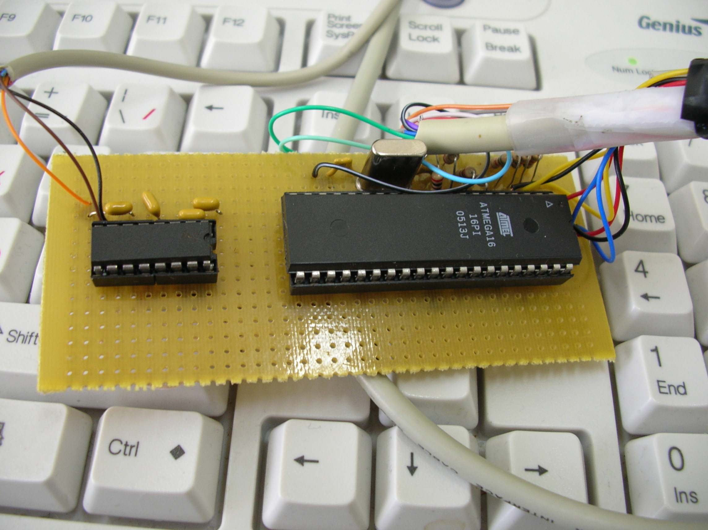
Prototype on Atmega16
Interceptor is capable to work as a WDT (watchdog timer) for PC. PC software can activate this function of the interceptor and it will short reset pins of the PC after certain timeout. To work properly, WDT must be reinitialized from the PC in time intervals less than WDT timeout.
Timeout can be set from 3.2 to 816 sec.
After system reset (by WDT or by direct command) keyboard will be blocked automatically, WDT timeout will be changed to 5 minutes, WDT will be left activated. This is done in case of system hanging during reboot.
Interceptor is capable to recognize abrupt PC reboots by the state of DTR pin in serial port (this feature is disabled by default).
After standard system boot up, PC software should open serial port and keep it open. There will be logical 1 on DTR pin in this case. During reboot serial port will be reinitialized and the state of DTR pin will be changed. In this case interceptor will block the keyboard.
After activation, DTR function will be automatically deactivated after the first successful detection of PC reboot.
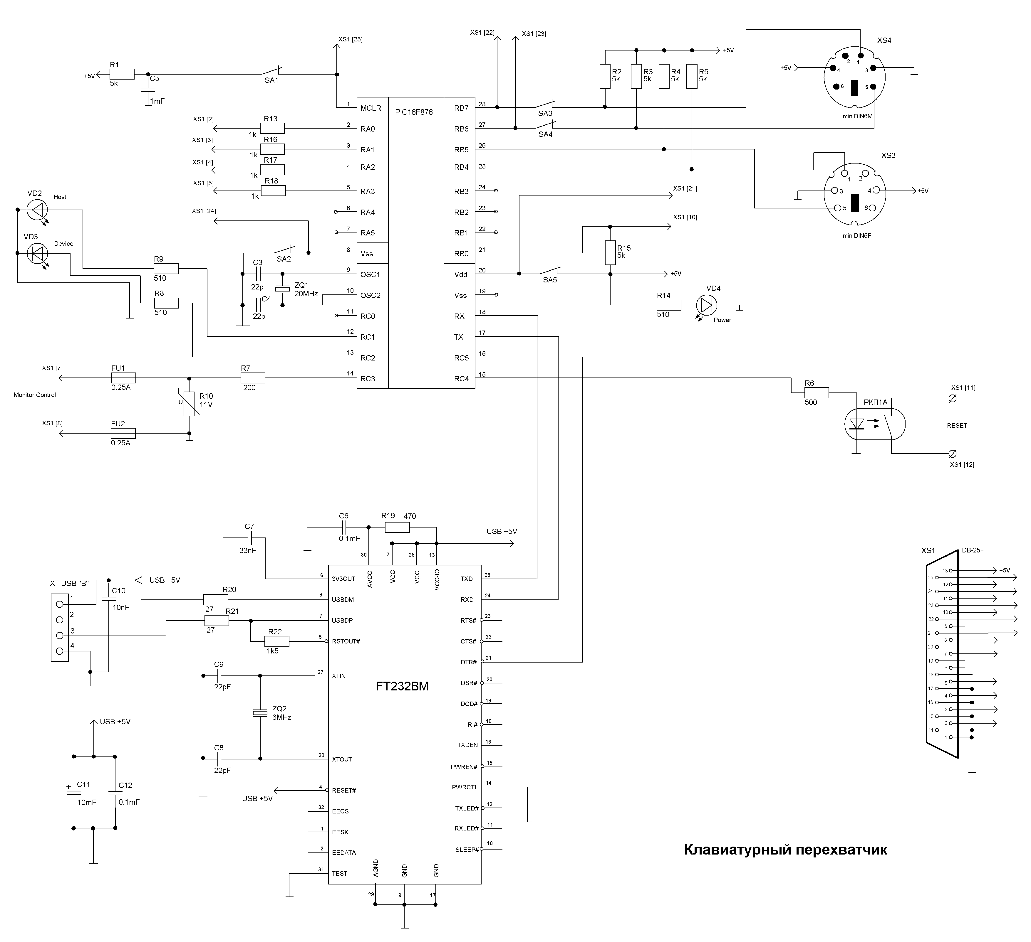
PS/2 keyboard Interceptor schematics
Switches SA1-5 were never exist.
Upon power on, PC and interceptor is switching on simultaneously. After the short period of time, less than 50mcs, interceptor will have initialized and will have started to filter scancodes using default mode. In this mode key scancodes can’t reach the Host but service communications is possible.
After standard system boot up, PC software should configure the interceptor by setting WDT timeout, enabling/disabling WDT function, enabling DTR control and unlocking keyboard.
All commands to interceptor are consist of two bytes. Gap in transmission between bytes must be less than 7ms, baud rate must be 19200, one stop bit, 8 data bits, no parity.
Device has 4-byte status response which consist of:
0 byte – header ‘11110000’
1st byte:
7 bit: keyboard state (0 – blocked, 1 – unblocked)
6 bit: WDT state (0 – off, 1 – on)
5 bit: DTR control state (0 – DTR control disabled, 1 – DTR control enabled)
4 bit: TFT monitor state (0 – monitor is disabled, 1 – monitor is enabled)
3 bit: events from push button (0 – there were no events since last poll, 1 – there is an event)
2 bit: current state of the push button (0 – released, 1 – pushed)
1 bit: not used
0 bit: not used
2nd byte
holds a decimal number of WDT prescaler. The product of this number an 3.2 gives a number of seconds before the system reset by initialized WDT.
3rd and 4th bytes
hold 10 bits of data from ADC which is connected to analogue thermal sensor. This resolution allows to read temperature up to 0.25C precision.
Filtering of PS/2 protocol by this device is not perfect. Sometimes errors happens. Some of them harmless or at least imperceptible. Some of them cause a wrong PS/2 protocol state and should be detected and rectified.
Some counters were added for debugging purposes and their values are sent together with status data.
All these counters have to do with PS/2 protocol.
1) How many times Host blocked the line before interceptor started transmission
2) as (1) but Host didn’t use this state to send something, just delayed transmission.
3) How many times information were lost i.e. Host blocked transmission from interceptor and raised RTS (request to send) condition
4) How many times “flag-keys error cleaner” procedure was activated. Theoretically must be equal to (3)
5) How many times the procedure of cleaning “the loss of extended command” were activated.
6) Code of byte which causes the last data loss.
Current firmware recognizes following 2-byte commands (all numbers are decimal):
Set timeout for system reset (WDT) [12, (0-255)]
Writes to EEPROM value of the timeout. Command consists of 2 numbers – operation code and timeout value.
Actual timeout in seconds is a product of mentioned timeout value and 3.2.
Command is acknowledged by 3 bytes [30, 37, (0-255)]. The latter byte is a timeout value that have been written.
Enable/reinitialize system reset by timeout (WDT) [56, 13]
Starts reset timer or reinitialize it using timeout written to EEPROM by previous command.
After timeout, if timer haven’t been stopped or reinitialized, keyboard is blocked and solid state relay, connected in parallel to PC reset button, is switched on.
Command is acknowledged by [35, 42]
Disable system reset by timeout [79, 15]
Stops timer that is used for system reset.
Command is acknowledged by [45, 52]
Direct system reset [62,22]
Switches on the relay, connected in parallel to PC reset button. Operation is performed immediately, without any timeout.
Command is acknowledged by [40, 47]
Direct keyboard lock [72, 42]
Blocks all non-service codes from keyboard.
Command is acknowledged by [15, 22]
Keyboard unlock [75, 24]
Allows keyboard to communicate freely with Host.
Command is acknowledged by [20, 27]
Lock keyboard by DTR state [82, 14]
Activates control of DTR pin of serial port.
Fired only once. This function is deactivated right after detection of low level on DTR pin.
Command is acknowledged by [50, 57]
Disable DTR control [85, 16]
Disables control of DTR pin in serial port.
Command is acknowledged by [55, 62]
Switch LCD monitor on [95, 99]
Switches on the solid state high voltage relay.
This relay can be used for any load, not just a monitor.
Command is acknowledged by [120, 28]
Switch LCD monitor off [95, 99]
Switches off the solid state high voltage relay.
Command is acknowledged by [110 ,18]
Get status [115, 132]
Requests status message.
Clear push button event [140, 162]
Clears “case has been opened” event.
Command is acknowledged by [130, 130]
Download
ASM file with firmware.
Schematics of the main part in Splan format
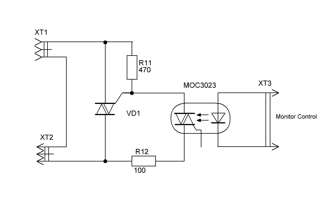
Schematics for monitor control in Splan format.