This is the last chapter about led message boards.
The highest point of their evolution (I mean, this particular kind, of course 🙂 ), guided by me 🙂
At the end we concluded that the most usable size for our message boards is 7x64px.
We had been experimenting with different matrix sizes and different LED types but the most demanded and the easiest to produce was red, 5mm LED, 7×64 px. message boards.
The height of 7 pixels was selected because 7×5 px fonts were the most common and these fonts have good ratio of letter width to readability.
So, using 7×5 font you can fit maximum letters on the screen and still have a good readability.
We also had been experimenting with different LED types such as Piranha. The only video I have of the board’s last version controller is the video where I am testing matrix fragment on Piranha LEDs.
This chapter won’t have any Proteus simulations or even schematic diagram.
They are not very different from 8×128 message board except that shift registers were replaced by specialized LED drivers MBI5024.
For PCB creation I used SprintLayout software.
PCB had one layer and all additional connections were made by wires.
Actually, there are two PCBs inside layout file. The main PCB and additional. Additional PCB can be connected to the main in series and contains only LED controllers.
So, the second PCB can be used to extend the width of the message board with slight changes in software.
Here is my final PCB image but I can’t guarantee that it is correct 🙂 It’s been a long time since.
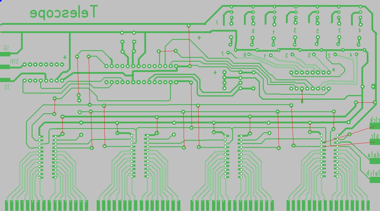
Main PCB
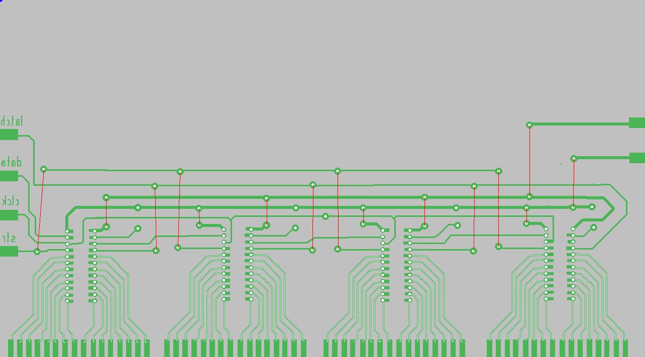
Additional PCB
As I can see on the images – I didn’t use any capacitors for MAX232 – I think that is because I used simplex type of communication. There were no acknowledges from PIC to PC so there was no need in charge pump for MAX232.
Also in this version decoder, which selects rows, is switched on and off by software. I do not remember how it was made 🙂
I hope I used some version of decoder that had a “disable” pin and didn’t use PIC’s leg to power it…
Unfortunately, as I can see, ASM file contains “programmatically enabled decoder” but PCB layout doesn’t.
Anyway, as I remember, the whole mess with delays between row switching and attempts to completely disable decoder, when the new row is being prepared, was because of slight flickereng of previous, already deactivated row. Now I think (thanks to Proteus simulations) that the problem was in column transistors that had no ground bias path. I think that simply adding a resistor between base and emitter of those transistors will remove flickering.
So I post here a few blurred images of the last version of controller, PCB layout file and slightly brushed ASM file. That’s all I have now 🙂
Character generator inside ASM file should be created automatically and it’s content almost the same as here, except commands for speed changing and pauses.
Downloads:
ASM file.
PCB file for SprintLayout